Voltage, Current, & Resistance
Voltage
We define
voltage as the amount of potential energy between two points on a circuit. One
point has more charge than another. This difference in charge between the two
points is called voltage. It is measured in volts, which, technically, is the
potential energy difference between two points that will impart one joule of
energy per coulomb of charge that passes through it (don’t panic if this makes
no sense, all will be explained). The unit “volt” is named after the Italian
physicist Alessandro Volta who invented what is considered the first chemical
battery. Voltage is represented in equations and schematics by the letter “V”.
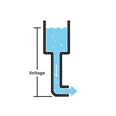
When
describing voltage, current, and resistance, a common analogy is a water tank.
In this analogy, charge is represented by the water amount, voltage is
represented by the water pressure, and current is represented by the
water flow. So for this
analogy, remember:
·
Water = Charge
·
Pressure = Voltage
·
Flow = Current
Consider a
water tank at a certain height above the ground. At the bottom of this tank
there is a hose.
The pressure at the end of the hose
can represent voltage. The water in the tank represents charge. The more water
in the tank, the higher the charge, the more pressure is measured at the end of
the hose.
We can think
of this tank as a battery, a place where we store a certain amount of energy
and then release it. If we drain our tank a certain amount, the pressure
created at the end of the hose goes down. We can think of this as decreasing
voltage, like when a flashlight gets dimmer as the batteries run down. There is
also a decrease in the amount of water that will flow through the hose. Less
pressure means less water is flowing, which brings us to current.
Current
We can think
of the amount of water flowing through the hose from the tank as current. The
higher the pressure, the higher the flow, and vice-versa. With water, we would
measure the volume of the water flowing through the hose over a certain period
of time. With electricity, we measure the amount of charge flowing through the
circuit over a period of time. Current is measured in Amperes (usually just referred
to as “Amps”). An ampere is defined as 6.241*1018 electrons (1 Coulomb) per second
passing through a point in a circuit. Amps are represented in equations by the
letter “I”.
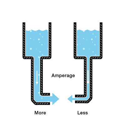
Let’s say now
that we have two tanks, each with a hose coming from the bottom. Each tank has
the exact same amount of water, but the hose on one tank is narrower than the
hose on the other.
We measure the
same amount of pressure at the end of either hose, but when the water begins to
flow, the flow rate of the water in the tank with the narrower hose will be
less than the flow rate of the water in the tank with the wider hose. In
electrical terms, the current through the narrower hose is less than the
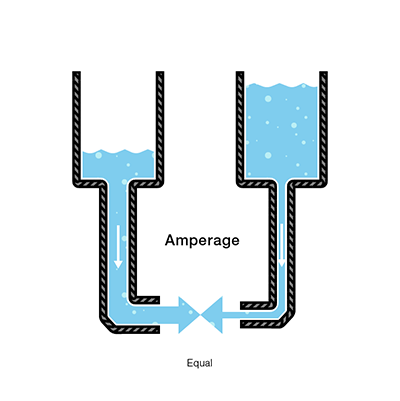
current through the wider hose. If we want the flow to be the same through both
hoses, we have to increase the amount of water (charge) in the tank with the
narrower hose.
This increases
the pressure (voltage) at the end of the narrower hose, pushing more water
through the tank. This is analogous to an increase in voltage that causes an
increase in current.
Now we’re
starting to see the relationship between voltage and current. But there is a
third factor to be considered here: the width of the hose. In this analogy, the
width of the hose is the resistance. This means we need to add another term to
our model:
·
Water = Charge
(measured in Coulombs)
·
Pressure = Voltage
(measured in Volts)
·
Flow = Current
(measured in Amperes, or “Amps” for short)
·
Hose Width = Resistance
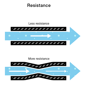
Resistance
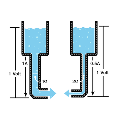
Consider again
our two water tanks, one with a narrow pipe and one with a wide pipe.
It stands to
reason that we can’t fit as much volume through a narrow pipe than a wider one
at the same pressure. This is resistance. The narrow pipe “resists” the flow of
water through it even though the water is at the same pressure as the tank with
the wider pipe.
In electrical
terms, this is represented by two circuits with equal voltages and different
resistances. The circuit with the higher resistance will allow less charge to
flow, meaning the circuit with higher resistance has less current flowing
through it.
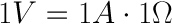
This brings us
back to Georg Ohm. Ohm defines the unit of resistance of “1 Ohm” as the
resistance between two points in a conductor where the application of 1 volt
will push 1 ampere, or 6.241×10¹⁸ electrons. This value is usually
represented in schematics with the greek letter “Ω”, which is called omega, and
pronounced “ohm”.